INJECTION MOULDING
Injection moulding parts and injection tools. Full solutions from design to production.
What to Consider for Injection Molding Polyethylene - polyethylene moulding
Author:gly Date: 2024-10-15
Although the coloring processes are optional in the plastic injection mold manufacturing stages, today, the color preferences are among the processes that are decided before the manufacturing process. In addition, the most common rules that should be known in the manufacture of plastic molds are as follows;
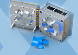
Plastic injection mold manufacturing is a very popular technological process that facilitates plastic production. Plastic molding, which is increasing day by day, is defined as the creation of product templates by combining the determined parts with the help of machinery. Construction phase of plastic injection molding is the process of melting plastics in a plastic injection molding machine and then injecting them into a mold under high pressure. In this process, the material is cooled, solidified, and then the two halves of the mold are opened and released. Plastic molds are obtained in desired sizes and molds.
The parts involved in the mold manufacturing process need to be carefully designed to facilitate production. Products made in plastic injection machines are primarily designed by an industrial engineer or a designer. The advantages of plastic injection mold manufacturing provide long-term convenience. It minimizes the need for maintenance, especially by enabling mass production and being manufactured from special steel. Mold manufacturing, which also offers the opportunity to obtain many products, is very popular in every sector. The first disadvantage that we come across is the cost. Production process of the plastic molds can take some time. The requirement for a qualified workmanship, expensive workbenches and equipment increase the costs. Another disadvantage is that the plastic mold period is long in cases where the production phase needs to be accelerated. For detailed information about plastic injection mold manufacturing, you can contact the Moldmore expert team.

3) In cases where the slide rod is screwed directly into the slide body, make sure wrench flats can be easily accessed for assembly, or use a double-rod-end cylinder. 4) “T” style couplings can be used to secure the cylinder rod end to the slide. (Refer to drawing S2-3) 5) Unless otherwise specified by the Customer, use Parker “EPS” style solid-state proximity switches.
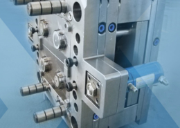
Contents: A) Mechanical injecion mold Slide Design Standards B) Hydraulic injecion mold Slide Design Standards B) Injection Mold Lifter Standard


2) Parker series 2-H hydraulic cylinders will be used. The selection of cylinder bore size and cylinder mount style will be determined by slide size, amount of molding surface (injection pressure), and sequence of hydraulic pull and set. DO NOT USE PARKER MOUNTING STYLE “J” or “JB” DUE TO THE DECREASE IN PRESSURE RATING.
1) Whenever possible use the Progressive Standard Unilifter Round Core Blade Undercut Release System with a standard Progressive head detail or a custom manufactured head detail retained to the rod portion of the assembly with a rolled dowel. All Progressive Application Guidelines must be adhered to. 2) The head design of the lifter must have a minimum of 3-degrees shut-off. 3) Maximum angle acceptable for lifter travel is 11 degrees without special design considerations. 4) Provide a .003” to .005” pad on top of the lifter to prevent part “drag”. 5) Most parts will have a tendency to “ride” with the lifters (remaining on the detail formed by the lifters), which will not let the parts fall free. In situations where there are no details/side walls to retain the parts, consider extending ejector pins into the wall section and/or add “gripper” details to the face of the ejectors (REQUIRES THAT EJECTOR PINS BE KEYED). Molded guide posts can also be considered, but must be approved by the Customer.
Moldmore is a company that has been manufacturing molds for over thirty years. It is specialized in thin wall plastic containers and lids. Most of these molds are manufactured according to the in-mold labeling system.
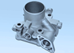
Plastic mold manufacturing is a technological process that takes place with the completion of various stages. Plastic Injection Mold Manufacturing Production stages:
A) Mechanical injecion mold Slide Design Standards (refer to drawing S2-1 & S2-2): 1) All shut-off surfaces must have a minimum of three degrees draft in direction of slide travel. Any shut-off angle less than three degrees must have written customer approval. 2) Two angle pins will be required on any slide design that exceeds seven inches in length. Consider a center Slide Guide for all long slides. 3) There must be a minimum of three degrees difference between the angle pin and back wedge. 4) The back wedge surface of the slide must have a lamina bronze (preferred) or 0-1 steel wear plate to allow for adjustment and for maintenance of wear surfaces. 5) The back wedge must be designed to resist injection pressure by backing up the entire molding surface. A double-wedge design must be considered for all large molding surfaces. 6) There must be a minimum of 0.20” ( 0.37” preferred ) clearance between slide detail and the molded part when slide is in the back position. 7) There can be no ejection under the slide detail without written Customer approval. If the customer accepts ejection under the slide detail, limit switches must register both forward and back movement of the ejector system. 8) Slides that mold large areas of part shape must have sufficient cooling. Consider Mold Max sub-inserts for difficult to cool details. 9) All deep rib details must be sub-inserted for venting. 10) Consider spring-loaded slide face ejection for all long wall or deep rib details. 11) Superior slide locks of sufficient weight retention can be used for slide retention in the back position. 12) Slides with flat faces that engage the cavity in direction of slide travel must be designed with face-loaded or external springs to prevent gaulding. In designs with slides on the “TOP” of mold, slide-face-mounted or external spring designs are to be used instead of Superior slide locks. 13) There must be a minimum of 6-points hardness (RcC) between the Gib material and the slide material. 14) The length of the slide foot must be 50% of the overall height of the slide. B) Hydraulic injecion mold Slide Design Standards 1) All mechanical slide design standards relative to shut-off, molding surfaces, and cooling will apply to the Hydraulic Slide designs.
LK-Mould Ltd.,
No.15, JinShen Road, Jin xia District
Changan Town, Dongguan
523850 Guangdong
China